Modbus
Modbus is a common protocol for communication with industrial devices. This implementation is based on version 1.1b3.
The Modbus Target is split in two communication modes: Modbus TCP and Modbus Serial (RTU).
Modbus TCP Configuration
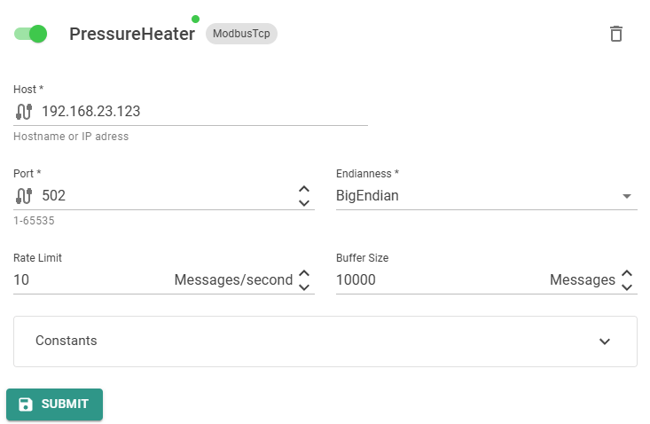
The Modbus TCP Target has the following parameters:
Host: Host name or IP Address of the client.Port: Client. Default is502.TargetType: The type is alwaysModbusTcpfor this Target.Endianness: Byte endianness. Can beBigEndian,LittleEndian,BigEndianFlippedorLittleEndianFlipped. The flipped variants swaps the two bytes in a Modbus register.
For the common parameters, see the Introduction.
Corresponding Edge configuration and Device Twin definition to activate the Modbus TCP Target service:
- Edge-UI
- Device Twin
PV Inverter is in this example the Name of the Target. This can be any unique name.
{
  "PV Inverter": {
    "Port": 502,
    "Host": "192.168.1.133",
    "TargetType": "ModbusTcp",
    "Endianness": "BigEndian",
    "MessagesPerSecondLimit": 1.0,
    "BufferSize": 1,
    "Constants": {},
    "Enabled": true
  }
}
Modbus Serial (RTU) Configuration
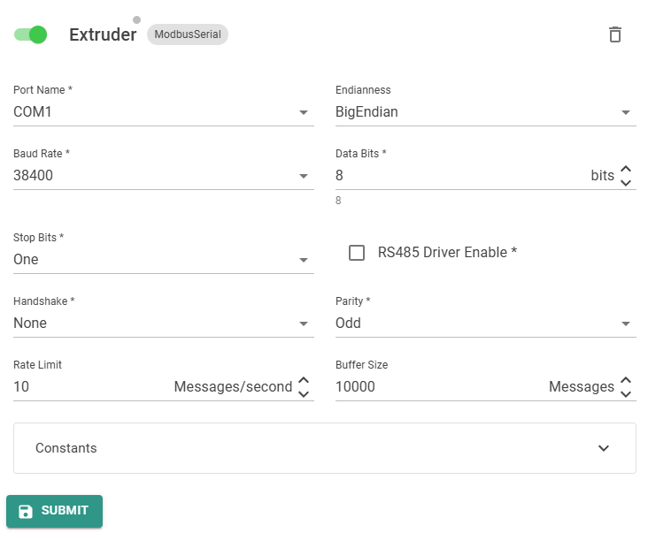
The Modbus Serial Target has the following parameters:
PortName: Port name of the serial port. E.g.COM1Endianness: Byte endianness. Can beBigEndian,LittleEndian,BigEndianFlippedorLittleEndianFlipped. The flipped variants swaps the two bytes in a ModbusBaudRate: Serial baud rate. Can be4800,9600,19200,38400,57600,115200DataBits: Number of data bits. Default is8.StopBits: Number of stop bits. Can beOne,TwoorOnePointFiveRs485DriverEnable: EnableRS485mode.Handshake: Can beNone,XOnXOff,RequestToSendorRequestToSendXOnXoffParity: Can beNone,Odd,Even,MarkorSpaceTargetType: The type is alwaysModbusSerialfor this Target.
For the common parameters, see the Introduction.
Corresponding Edge configuration and Device Twin definition to activate the Modbus Serial Target service:
- Edge-UI
- Device Twin
Extruder is in this example the Name of the Target. This can be any unique name.
{
  "Extruder": {
    "PortName": "COM3",
    "BaudRate": 38400,
    "DataBits": 8,
    "StopBits": "One",
    "Rs485DriverEnable": false,
    "Handshake": "None",
    "Parity": "Odd",
    "TargetType": "ModbusSerial",
    "Endianness": "BigEndian",
    "MessagesPerSecondLimit": 1.0,
    "BufferSize": 1,
    "Constants": {},
    "Enabled": false
  }
}
Data Streaming
Modbus is a address based protocol, therefore no discovery or name based signal access is possible. The syntax for the signal name is: Name,DeviceId,Address,RegisterType,DataType,ArrayLength. The fields DataType and ArrayLength are optional.
Name: The output signal name.DeviceId: The Device ID of the Modbus device.Address: The start address of the signal to read.RegisterType: Type of the Modbus registerdi: Discrete Inputsc: Coilir: Input Registerhr: Holding Register
DataType(optional when connecting to Coils or Discrete Inputs)x:Boolean. When reading a register, the bit position can be added in square brackets. E.g.x[5].b:Bytew:UInt16dw:UInt32lw:UInt64si:SBytei:Int16di:Int32li:Int64r:Floatdr:Doublec:Char ASCII (1 Byte)wc:Char Unicode (2 Bytes)s:String ASCII (1 Byte). The length of the string must be added in square brackets. E.g.s[12].ws:String Unicode (2 Bytes). The length of the string must be added in square brackets. E.g.ws[12].
ArrayLength: Length of the array to read. If not present, it defaults to1.
Endianness
The byte endianness can either be set globally in the Target settings or at signal level. Therefore, add
.be(Big Endian),.bef(Big Endian, flipped bytes in Modbus register),.le(Little Endian) or.lef(Little Endian, flipped bytes in Modbus register)
to the DataType.
The Signals to read or write are configured in the Router.
For information how signals are named and labeled in Data Lakes, please read the Data Lake documentation.